 English
 Espaol
 Franais
 阿拉伯
阿拉伯 中文(簡(jiǎn))
 Deutsch
 Italiano
 Português
 日本
日本 韓國(guó)
 български
 hrvatski
 esky
esky Dansk
Dansk Nederlands
 suomi
suomi Ελληνικ
 印度
印度 norsk
norsk Polski
 Roman
Roman русский
 Svenska
 我們是專業(yè)的強(qiáng)鹿柴油機(jī)機(jī)油泵的拆卸、檢查和安裝標(biāo)準(zhǔn)技術(shù)規(guī)范參數(shù)服務(wù)商,想要了解更多的強(qiáng)鹿柴油機(jī)機(jī)油泵的拆卸、檢查和安裝標(biāo)準(zhǔn)技術(shù)規(guī)范參數(shù)類型和資料與費(fèi)用,請(qǐng)現(xiàn)在聯(lián)系我們!寧波日昕動(dòng)力科技有限公司

首頁
產(chǎn)品展示>強(qiáng)鹿柴油機(jī)機(jī)油泵的拆卸、檢查和安裝標(biāo)準(zhǔn)技術(shù)規(guī)范參數(shù)
強(qiáng)鹿柴油機(jī)機(jī)油泵的拆卸、檢查和安裝標(biāo)準(zhǔn)技術(shù)規(guī)范參數(shù)
詳細(xì)描述
John Deere約翰迪爾強(qiáng)鹿柴油機(jī)機(jī)油泵的拆卸、檢查和安裝標(biāo)準(zhǔn)技術(shù)規(guī)范參數(shù)
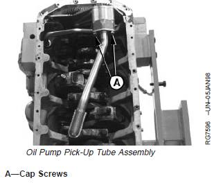
A loose or damaged suction tube or O-ring can cause a
temporary loss of prime for the engine oil pump at
start-up. There will be low or no oil pressure at starting,
followed by normal engine oil pressure.
NOTE: If the pick-up tube is to be inspected only and not
removed, verify mounting cap screw torque to
ensure proper seating and seal.
1. Remove oil pan.
2. Loosen cap screws (A) and remove oil pump pick-up
tube assembly.
3. Inspect pick-up tube for cracks, restrictions or damage.
Replace if necessary.
4. Install assembly with new O-ring and tighten cap
screws to specifications.
Specification
Oil Pump Pick-Up Tube Cap
Screws—Torque.............................................................. 35 N•m (26 lb-ft)
5. Reinstall oil pan. (See INSTALL OIL PAN, later in this
group.)
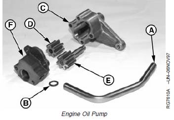
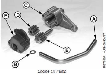
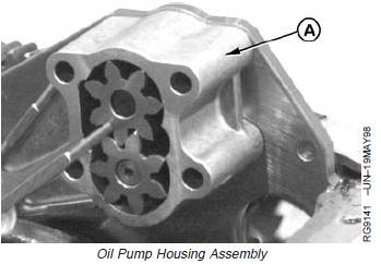
Engine Oil Pump Assembly
A—Outlet Tube
B—O-Ring
C—Pump Housing
D—Idler Gear
E—Drive Gear
F—Cover
Remove Engine Oil Pump
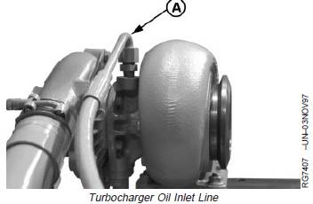
1. Drain oil and disconnect turbocharger oil inlet line (A)
at the turbocharger.
2. Remove oil pan.
3. Remove gasket from oil pan and oil pan rail.
A—Oil Inlet Line
4. On 4-cylinder engines with balancer shafts, lock
crankshaft at TDC using JDE81-1 or JDE83 Flywheel
Turning Tool and JDG1571 or JDE81-4 Timing Pin.
Then lock the balancer shaft (injection pump side)
using a lock-grip pliers so that balancer shaft cannot
turn while oil pump gear is being removed.
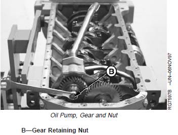
IMPORTANT: When removing nut and gear from
tapered oil pump drive shaft, take care
not to damage fine threads on end of
shaft.
5. Remove nut (B) and pull gear from tapered oil pump
drive shaft.
To remove oil pump gear, loosen nut several turns and
apply force between the front plate and gear on two
sides of gear with pry bars.
If above method does not work, loosen oil pump
housing cap screws and strike the nut on end of shaft
with a small lead hammer while applying force to gear
until gear is free of tapered shaft.
6. Remove oil pump pick-up tube. (See REMOVE,
INSPECT, AND INSTALL OIL PUMP PICK-UP TUBE
ASSEMBLY in this group.)
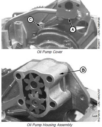
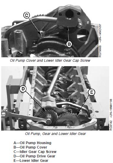
7. Remove upper two cap screws and remove cover (A).
NOTE: The lower idler gear cap screw (C) has to be
removed to remove the oil pump housing.
8. Loosen idler cap screw (C).
9. Remove lower oil pump housing cap screws and turn
idler cap screw (C) out while removing oil pump
housing assembly (B).
A—Cover
B—Oil Pump Housing
C—Idler Cap Screw
Inspect and Measure Clearances
Inspect oil pump components for excessive wear. Replace
parts or oil pump assembly, as necessary.
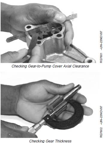
1. Check gear-to-pump cover axial clearance.
Specification
Oil Pump Gears—Thickness 35.975—36.025 mm
(1.4163—1.4183 in.)
.....................................
Oil Pump Gears—Axial Clearance 0.045—0.165 mm
(0.0018—0.0065 in.)
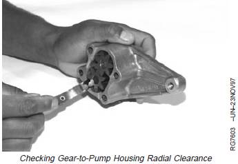
2. Check gear-to-pump housing radial clearance.
Specification
Oil Pump Gears—Radial
Clearance 0.131—0.211 mm
(0.005—0.008 in.)
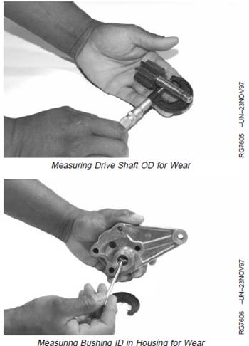
3. Check housing and cover bore ID and shaft OD.
Inspect cover and housing for evidence of gear rub.
Light contact is acceptable.
4. Measure bushing ID in housing and bore in cover.
Specification
Oil Pump Drive Shaft—OD 16.017—16.037 mm
(0.6306—0.6314 in.)
........................................
Oil Pump Bushing in Housing—ID 16.052—16.102 mm
(0.632—0.634 in.)
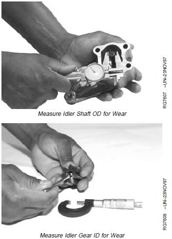
5. Measure idler shaft OD and idler gear ID
Specification
Oil Pump Idler Shaft—OD 12.316—12.332 mm
(0.4849—0.4855 in.)
.........................................
Oil Pump Idler Gear—ID 12.355—12.363 mm
(0.4864—0.4867 in.)
Complete Oil Pump Disassembly
1. Remove O-ring from pump housing and cylinder block
(for outlet tube).
2. Remove O-ring from oil pick-up tube.
3. Clean oil pump parts in solvent. Dry with compressed
air.
4. Inspect pick-up tube. Check flange-to-pick-up tube
weld for cracks. If cracks or other defects are found,
replace pick-up tube. (See REMOVE, INSPECT AND
INSTALL OIL PUMP PICK-UP TUBE ASSEMBLY, in
this group.)
Assemble Engine Oil Pump
A—Outlet Tube
B—O-Ring
C—Pump Housing
D—Idler Gear
E—Drive Gear
F—Cover
IMPORTANT: Lubricate gears and shaft with clean
engine oil before assembling.
1. Install new O-ring (B) in pump cover (F).
2. Put idler gear (D) and drive gear (E) in pump housing
(C).
發(fā)動(dòng)機(jī)機(jī)油泵的安裝
NOTE: This procedure is for installing the oil pump with
timing gear cover installed. If timing gear cover is
removed from engine, refer to INSTALL AND
TIME BALANCER SHAFTS (4-Cylinder Engines)
in Group 050.
1. On 4-cylinder engines with balancer shafts, lock No. 1
piston at TDC compression stroke.
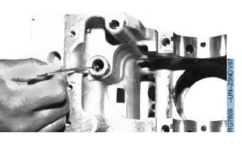
2. Install new O-rings in cylinder block and oil pump cover
(for outlet tube). Install tube into cover and block.
3. Lubricate lower idler gear cap screw threads (C) and
draw into leg of housing finger tight while installing oil
pump housing (A) with gears onto front plate.
4. Wedge a hardened round punch between the drive
gear and idler gear.
5. Install oil pump drive gear (D) so that it meshes with
lower idler gear (E) and balancer shaft gear (4045
engines only) without altering gear train timing.
6. Install new retaining nut and tighten to specifications.
Specification
Oil Pump Drive Gear “Staked”
Nut—Torque .................................................................... 50 N•m (37 lb-ft)
7. Stake oil pump drive gear nut by applying three center
punch marks near ID of shaft.
8. Swing (position) oil pump cover (B) onto pump housing
and install two lower cap screws finger tight.
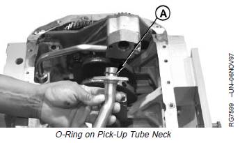
9. Install new O-ring (A) on neck of pick-up tube. Install
pick-up tube. (See REMOVE, INSPECT, AND
INSTALL OIL PUMP PICK-UP TUBE ASSEMBLY in
this group.)
A—O-Ring
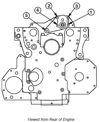
NOTE: Idler gear cap screw threads (5) must be
lubricated.
10. Tighten four cap screws and lower idler gear cap
screw to specified torque according to sequence
shown.
Specification
Oil Pump-to-Front Plate and Oil
Pump Pick-Up Tube Cap
Screws—Torque.............................................................. 35 N•m (26 lb-ft)
Oil Pump Lower Idler Gear Cap
Screw (Lubricated Threads)—
Torque ............................................................................. 70 N•m (53 lb-ft)
免費(fèi)熱線
400-100-8969???15088860848
400-100-8969???15088860848
機(jī)組銷售
0574-26871589? 15267810868
0574-26871589? 15267810868
配件銷售
0574-26886646? 15706865167
0574-26886646? 15706865167
維修熱線
0574-26871569 18658287286
0574-26871569 18658287286
手機(jī)端

微信公眾號(hào)
在線客服